Introduction
A pyro driver must deliver a decent amount of current from a battery to a electronic match (e-match) to ignite it.
There are several considerations in making a good pyro driver
- High current capacity. An e-match can consume ~200 mA to 2 A over ~300 ms. This is a significant amount of current for a significant amount of time, which can be considered close to DC/steady-state operation. Appropriate MOSFETs with large current capacity should be chosen
- Gate drive voltage. We need to minimize R_ds(on) since a large amount of current is going through the MOSFET. This means driving the gates at high voltages, or using a logic-level MOSFET.
- Inductance. A e-match may be positioned far away from the altimeter through some wires, therefore inductance effects such as flyback current should be considered.
- Brownout protection. If the microcontroller (MCU) and pyros are on the same battery, the pyros may cause a brownout/voltage drop on the MCU as the pyros draw a lot of current. This is a worst-case scenario, since it results in the MCU resetting. The pyro driver should be disabled on low voltage, either when the MCU detects brownout or some hardware.
- E-match blowing closed. When an e-match is ignited, they usually blow open, which results in the e-match not drawing anymore current. There is a chance it blows closed, which would result in excessive current draw if not dealt with.
- Safety. These gates must not prematurely fire under any circumstance. One example is some circuits may fire if the input voltage is too low (~1.5V).
For Neptunium, I have been designing several pyro circuits which are optimized for these parameters, and lower cost and space than Starcore’s pyro drivers.
Neptunium pyro driver v1
This is the first pyro driver circuit for Neptunium. Please forgive me for the terribly drawn LTspice schematics.
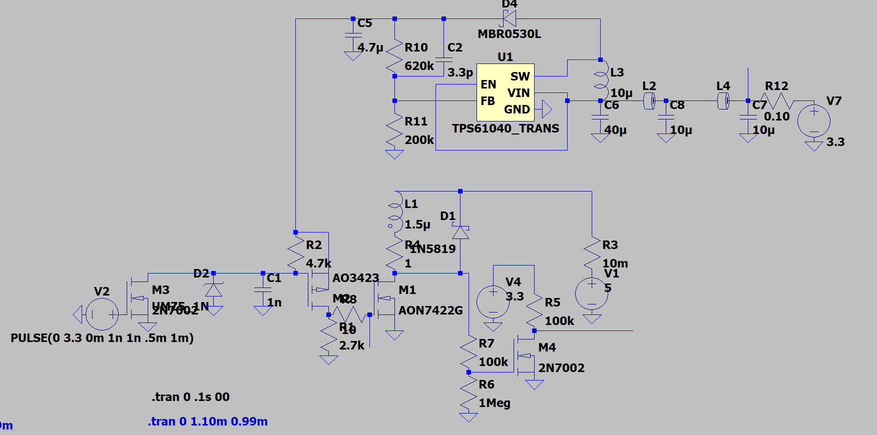
The top half of the circuit is a boost converter. The main power rail will be 3.3V, therefore we need to boost the voltage to 5V to minimize R_ds(on) by ensuring the gate is fully operating in saturation. While the MOSFET I chose can operate at 3.3V, it has has a relatively high R_ds(on) compared to V_gs > 4.5V.
The TPS61040 is chosen since it is available in JLCPCB’s basic parts list.
- The main issue with the boost converter is added power draw and it couples noise into the powerline. In the above schematic, the noise is reduced through a series of ferrite bead filters.
- A second issue is that this circuit MUST NOT exceed 5V, since it would damage the MCU’s GPIO (simulated by MOSFET M3 on the left). The buck-boost converter may have some ripple causing the voltage to increase above 5V. The TVS diode D2 is an attempt at capping this voltage overshoot.
The bottom-right part is a continuity test MOSFET. When there is an e-match loaded (represented by R4 and L1), M4 goes into high-impedance since the voltage divider will result in some voltage generated over the gate and source of M4. The voltage divider has large resistors to minimize current flow through the e-match, to prevent a misfire. A MOSFET is used instead of directly connecting the output of the voltage divider to a GPIO since Neptunium will have the option of using a separate pyro battery at a higher voltage to the MCU.
D1 is a flyback diode intended to suppress flyback current if the main power MOSFET M1 turns off, or if we PWM M1 to limit the average current (and heating) through the e-match and MOSFET.
Low resistance pull-downs/pull-ups are used on the gate drive circuit for M1, to minimize the risk of ESD or EMI causing the gate to build up charge and prematurely fire. This circuit only results in current passing through these resistors when the gates are firing, so this does not result in high quiescent current.
Neptunium pyro driver v2
🚧🚧Work in progress!🚧🚧
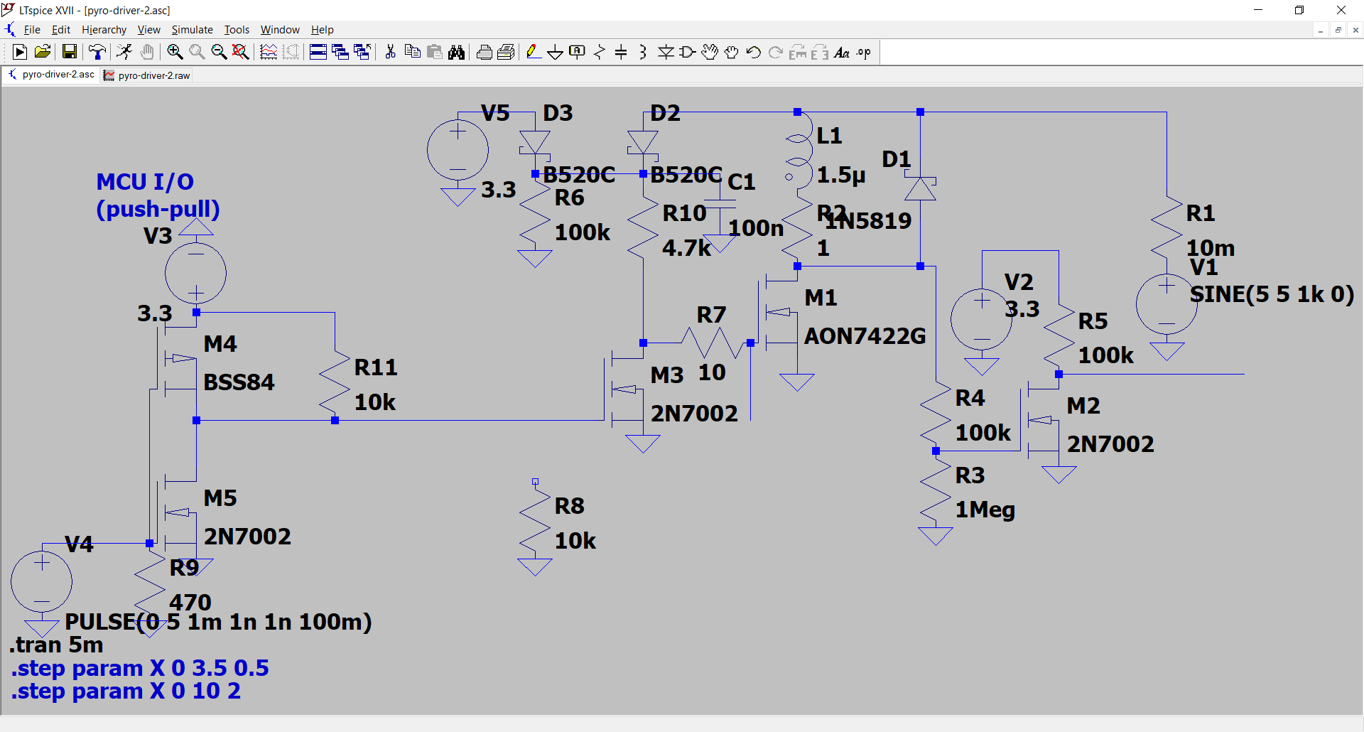 The main goal of this pyro driver is to remove the boost converter, since it introduces a lot of complexity and noise.